HV Metering Setup
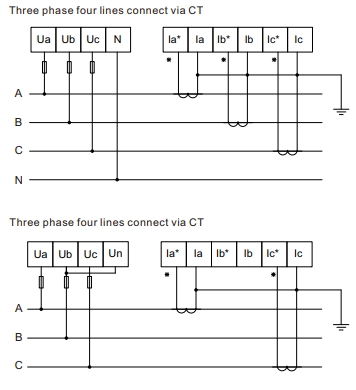
Differences between CT Wiring Configurations
| Feature | 3-Wire System | 4-Wire System |
|---|---|---|
| Number of CTs Required | 2 CTs | 3 CTs |
| Meter Setting | 3W3L | 4W3L |
| How to Connect Voltage Pins | All three phases, but join Phase 2 with neutral. This makes Phase 2 the reference point for voltage measurements. | All three phases and neutral separately. |
| How to Install CTs | CT1 and CT3 in opposite directions | All CTs in the same direction |
| Voltage Transformer Ratio | 27.5 (11kV) and 55 (22kV) because CTs are on the high voltage side | 1 |
| Power Calculation Method | Line to line voltage | Line to neutral voltage |
Important Installation Notes
Key Observations in 3-Wire Setup:
- Phase 2 power reading will show zero - this is normal and expected because it's used as the reference point
- Despite connecting 240VAC on the low voltage side, the meter display will show HV values (11kV or 22kV) - this is correct due to the PT ratio setting
- Power factor should remain accurate (close to 1.0) despite the voltage transformation
Single-Phase Power Measurement
In a single-phase system, power measurement is straightforward. We only need one Current Transformer (CT) to measure the current in the live conductor. The power is calculated by multiplying this current by the voltage between live and neutral:
Power = Voltage × Current
Three-Wire System
In a three-wire system (two phases with a common neutral), we only need two CTs to measure the power. This is because of Kirchhoff's Current Law: the sum of currents flowing into a node must equal the sum of currents flowing out.
In this case, the current in the neutral conductor (I₁ + I₂) can be derived from the measurements of the two phase conductors. Therefore, we don't need to measure it directly. The total power is simply the sum of the power in each phase:
Total Power = (V₁ × I₁) + (V₂ × I₂)
Phase 1
Phase 2
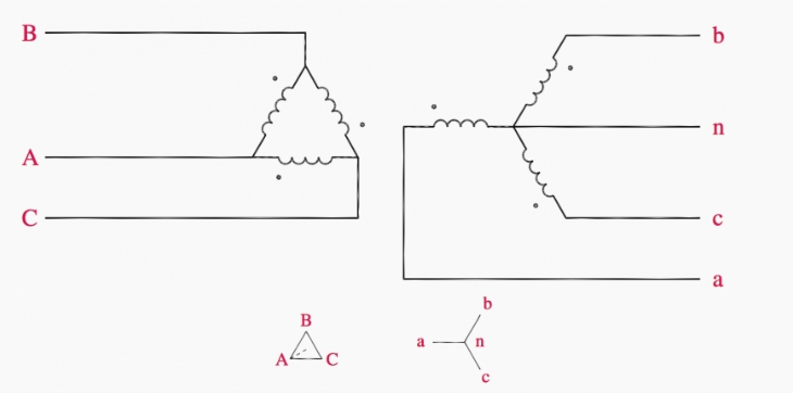
HV/LV Transformer Configuration
High voltage distribution transformers typically use a delta configuration on the primary (HV) side and a star configuration on the secondary (LV) side. This arrangement offers several advantages:
- Delta primary helps suppress harmonics and balances loads
- Star secondary provides a neutral point for single-phase loads
- Turns ratio determines the voltage transformation (typically 11kV:400V)
Transformer Configuration
Secondary (Star) Voltage
Phase-to-Neutral Voltages:
Phase-to-Phase Voltages:
Key Points:
- Primary (Delta): Line voltage = Phase voltage = 11kV
- Secondary (Star): Line voltage = Phase voltage × √3
- Phase-to-phase voltages lead phase-to-neutral by 30°
- Power remains constant across transformation
- Phase-to-neutral voltages lag line voltages by 30° but only when balanced
Delta to Star Conversion
In high voltage systems, equipment is often connected in a delta configuration. However, for measurement and safety purposes, we can convert this to a star (wye) configuration with a neutral point. This conversion maintains the same power transfer while allowing simpler measurements:
- Star voltage = Delta voltage ÷ √3
- Star current = Delta current × √3
Dominant current: Phase Y 86.6%
In this balanced 3-phase system:
- RMS values of each phase are equal (balanced)
- Instantaneous sum (IR + IY + IB) = 0 at every point in the cycle
Key Points
- Single-phase systems need one CT to measure power
- Three-wire systems need only two CTs
- The neutral current can be derived from the phase currents
- Delta-connected systems can be converted to star for easier measurement
- Power remains constant during delta-star conversion
- CT wiring can be configured with or without neutral current measurement